this section regarding resonance. Thanks in advance
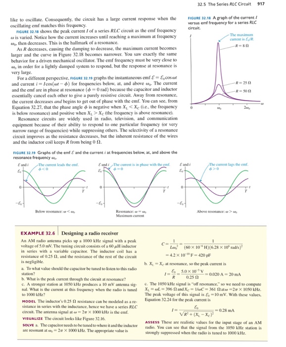
32.5 The Series RLC Circuit 917 like to oscillate. Consequently, the circuit has a large current response when the FIGURE 32.18 A graph of the current ! oscillating emf matches this frequency versus emf frequency for a series RLC FIGURE 32.18 shows the peak current Iof a series RLC circuit as the emf frequency ω is varied. Notice how the current increases until reaching a maximum at frequency The maximum current is ER then decreases. This is the hallmark of a resonance -851 As R decreases, causing the damping to decrease, the maximum current becomes larger and the curve in Figure 32.18 becomes narrower. You saw exactly the same behavior for a driven mechanical oscillator. The emf frequency must be very close to l in order for a lightly damped system to respond, but the response at resonance is very large For a different perspective. FIGURE 32.1, graphs the instantaneous emf E &cosar and current i = /cos(or-4) for frequencies below. at. and above ob-The current and the emf are in phase at resonance (φ = 0 rad) because the capacitor and inductor essentially cancel each other to give a purely resistive circuit. Away from resonance the current decreases and begins to get out of phase with the emf. You can see, from Equation 32.27. that the phase angle φ is negative when x.< xt (ie, the frequency is below resonance) and positive when X1Xe (the frequency is above resonance). R=25 Ω o Resonance circuits are widely used in radio, television, and communication equipment because of their ability to respond to one particular frequency (or very narrow range of frequencies) while suppressing others. The selectivity of a resonance circuit improves as the resistance decreases, but the inherent resistance of the wires and the inductor coil keeps R from being 012 FIGURE 32.19 Graphs of the emf E and the current i at frequencies below, at, and above the resonance frequency E and i Eandi/The current is in phase with the emf ε di currenn lags the emf Below resonance < Above resonance. ω > Maximam current EXAMPLE 32.6 Designing a radio receiver An AM radio antenna picks up a 1000 kHz signal with a peak voltage of 5.0 nW. The tuning circuit consists of a 60 H inductor in series with a variable capacitor. The inductor coil has a resistance of 0.25 Ω, and the resistance of the rest of the circuit is negligible. La., (60 × 10″H)(628 ×10° rad/s)” 4.2 × 10⁻¹⁰ F = 420 pF b. X X at resonance, so the peak current is a. To what value should the capacitor be tuned to listen to this radio station? b. What is the peak current through the circuit at resonance? c. A stronger station at 1050 k㎐ produces a 10 mv antenna sig- nal. what is the current at this frequency when the radio is tuned to 1000 kHz? c The 1050 kHz signal is- resonance so we need to compute XL-ωし= 396 Ω and Xc = 1/wC= 361 Ω ato,-2π × 1050 kHz The peak voltage of this signal is 10mV. With these values Equation 32.24 for the peak current is MODEL The inductor’s 025 Ω resistance can be modeled as a re- sistance in series with the inductance, hence we have a series RLC circuit. The antenna signal at ω >1000 kHz is the emf. 0.28 mA VISUALIZE The circuit looks like Figure 32.16. SOLVE a. The capacitor needs to be tuned to where it and the inductor are resonant at o2m x 1000 kHz. The ASSESS These are realistic values for the imput stage of an AM radio. You can see that the signal from the 1050 kHz station is strongly suppressed when the radio is tuned to 1000 kHz appropriate value is
ScholarMatic: Explanation & Answer
Your ready answer from a verified tutor is just a click away for as little as $14.99


Click Order Now to get 100% Original Answer Customized to your instructions!